

FIELD OF APPLICATION
Static calibration, using transfer torque wrenches, of torque transducers used for calibrating torque wrenches and screwdrivers.
Transfer torque wrenches are those devices that apply torque through a lever arm.
Therefore, this directive takes into account the relationship of deviating forces on the transducer in calibration, which are not taken into account in DIN 51309.
The procedure for classifying torque transducers is described.
The numbers below identify the paragraphs of the standard.
3. Characteristics
• All components of the instrument, including the cable, must be identified (manufacturer name, type, 4 or 6 wires, serial number, etc.)
• The nominal torque must be indicated
• The connection between the wrench and the calibration equipment must not introduce cross-forces or bending moments
• It shall be possible to modify the torque application point in the range of common torque wrenches
4.1 Calibration of torque transducers
• Calibration consists of applying torque to the calibrated device corresponding to practical use and recording measurements
• I can exchange the reading unit if the additional uncertainty due to the exchange is less than 1/3 of the relative uncertainty of the calibration result (SCS takes this into account in the uncertainty balance)
• Components and adapters must withstand 1.5 times the maximum torque transmitted
• At maximum torque the length variation of the measuring device and adapters must be less than 1 mm
• Before calibration the transducer and adapters must be charged at least 4 times with an overload of 8 to 12% of the nominal torque, for 1 to 1.5 minutes (for safety and to avoid damage during
4.2 Resolution of the indicating device
• The resolution r is the increment of the last active number, provided that the maximum fluctuation is 1 increment when the instrument is unloaded
• If the indication changes more than 1 increment, the resolution is half the fluctuation + 1 digit
• The minimum value of the measuring range is defined according to the class in the further table (classification criteria)
4.3 Preparation of the calibration
• All adjustments, if any, must be recorded
• Measurements shall be made after temperature stabilization
• The zero signal must be recorded before and after the calibration with unloaded torque in the vertical position
• Positive indication for clockwise torque
4.4 Calibration procedure
• Clockwise or counterclockwise calibration in the specified steps (usually 5 steps in the measuring range)
• We have defined a wait time of 10 seconds every step, as constant as possible
• Preload to nominal torque must be performed 3 times in the first cycle of the direction of calibration and once after each change of mounting position
• After each preload (short time) wait for zero stabilisation (max. 3 minutes) and record the value
• The ambient temperature must be between 18 and 28°C (preferably 22°C) and stable within ±1°C.
• The interval between two loading steps must be the same, especially in the presence of creeping
• The indication before measurement may be zeroed or taken into account in the calculation
• The indication shall be reset to zero at the beginning of each series of measurements
Number of required measuring series

The minimum number of torque stages (in addition to the zero stage) shall be as follow:
• class = 8 (suitably distributed over the measuring range)
Note: for exemple, in steps of 10, 20, 30, 40, 50, 60, 80 e 100 % ME or 2, 5, 10, 20, 40, 60, 80 e 100 % ME
• Class 0,5 = 5 (20, 40, 60, 80 e 100 % ME)
• classes 1 to 5 = 3 (20, 60 e 100 % di ME) (SCS procedure for class 1: 5 steps)
• The minimum value of the measuring range MA must be one of the calibration values
• The minimum number of torque stages depends on the class of the torque transducer, as shown in the table
• The first two ascending series determine repeatability in the same installation orientation
• A further ascending series determines the influence of the point of force application on the lever arm and on the calibration result
• A torque transducer can be calibrated for different measuring
Dependency of the lever arm lengths of torque wrenches on the rated torque

Changes in lever arm length
• To evaluate the influence of the point of application of the force to the lever arm, a series of lever arm length, mean and short lever, in function of the nominal torque (transfer wrenches only) are provided as in the table.
• For torques greater than 2000 N·m appropriate lever arm lengths will be selected
Sequence of calibration for class 1

4.4.7 Evaluation of the torque transducer
Reproducibility b, repeteability b’ and bl
• Reproducibility b is calculated for each calibration point as the difference between the increasing series at different mounting positions mean length of the lever arm
• The repeatability b’ is calculated for each calibration point as the difference between the increasing series in the same mounting position and the mean lever arm length
• The repeatability bl is calculated for each calibration point as the difference between the values of the second increasing series of mean lever arm length values and the series of values with minimum lever arm
Relative error of the zero signal f0
• The zero value shall be recorded prior to each increasing series and after each decreasing series.
• The zero value shall be read approximately 30 s after complete unloading
• The zero error f0 is calculated as the maximum absolute value of the difference between the two readings at all mounting positions
Reversibility (histeresis) h
• The reversibility error h(MK) is determined for each calibration torque as the maximum value of the absolute values of the differences between the indications of the increasing and decreasing series for each torque step
Interpolation error fa
• The interpolation error fa is determined with the aid of a smoothing function calculated through the origin point and in function of the calibration points used by means of an equation of 1st or 3rd degree
• The interpolation error is calculated for each calibration step as the difference between the calibration result and the associated value of the smoothing function
• For torque transducer with a defined scale display (such as torque transducer of SCS calibration benches), the display deviation fq is determined.
Indication error fq
• The indication deviation fq is only determined for torque transducers which display the result directly in the torque unit and for which an electronic adaptation of the indication to the interpolation function of the calibration result is not possible
• Represents the difference between the mean value of the increasing torques in the different mounting positions and the reference torque applied
Calibration result X
• The estimated value for each torque value represents the mean value of the results of the increasing torque measurement series with mean lever arm length
Principle of classification
The measuring range for which a certain class is assigned to the torque transducer comprises all calibration torques for which the corresponding classification criteria are met – from the upper limit of the measurement range to the smallest calibration torque
For the classification, the minimum value of the measurement range shall be:
• ≤ 20% of ME for all classes
Classification criteria
For the purposes of classification, the absolute quantities are converted into relative quantities according to the next table. The following criteria must thereby be taken into account:
• Range with the same installation orientation,
• Range with different installation orientations,
• Range with different lever arm lengths,
• Interpolation deviation or indication deviation,
• Zero-point deviation and
• Reversibility range.
Classification criteria for torque transducers
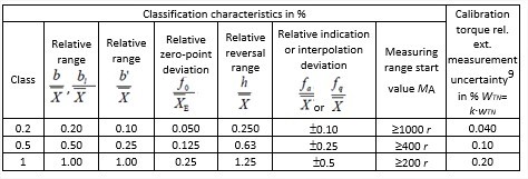
Our spreadsheet automatically checks all values to determine the class of the torque wrench.
Calibration certificate
We will later analyse in detail the calibration certificate, which must contain the following information at least
• Applicant,
• identity of all elements of the torque wrench calibration device and the torque introduction parts, as well as designation of the torque transfer standard,
• information concerning left and right torque, as well as lever arm lengths,
• classification result with listing of the associated measuring range and the relative measurement uncertainty according to Appendix B,
• estimate (mean values from the measured values of the upward series) and the balancing function,
• ambient temperature at which the calibration was performed,
• date of the calibration,
• information for identifying of the calibration laboratory,
• reference to this directive and
• orientation of the measuring axis during the calibration (horizontal and/or vertical).
For torque measurement devices with a defined scale (N·m), a declaration of conformity with the parameters required by a class is possible; for other devices, it is only possible by additionally indicating the equation of the interpolation curve
Period of validity
The maximum period of validity of the certificate must not exceed 26 months, but annual frequency is generally recommended, especially if there are particular traceability requirements or required by quality assurance regulations.
The torque transducer shall be re-calibrated:
• if it has undergone an overload which is higher than that applied during the overload test
• after corrective maintenance has taken place; or
• after an improper operation which can have an influence on the metrological properties or the measurement uncertainty.
Measurement uncertainty budget (according to DKD-R 3-8)
The relative standard measurement uncertainty w correlated to the torque M is given by:
 where:
![]()
• wKE is the uncertainty of the calibration system and also the various influences ∂M participate:
• δM1 Influence of the resolution r of the display unit on the calibration object
• δM2 Influence of the repeatability b‘
• δM3 Influence of the reproducibility b
• δM4 Influence of the reversibility range h
• δM5 Influence of the return to zero f0
• δM6 Influence of the force introduction conditions bl
• δM7 Influence of the indication or interpolation deviation fq or fa respectively
• δM8 Influence of the measurement uncertainty UKE of the torque calibration device, including a portion for long-time stability of the torque calibration device.
For undefined scale and use of linear equation or for defined scale the expanded uncertainty range W’ takes into account the deviations of interpolation fa or display fq as follows
![]() for undefined scale and use of linear equation
for undefined scale and use of linear equation
![]() for defined scale
for defined scale
The calculations are automatically performed on the spreadsheet and the results are given on page 4 of the calibration certificate (Table 8.1)
Reference uncertainty
This single calculation formula is considered with contributions as shown in the table:


These calculations are processed in the spreadsheet and the result is taken into account in the calculation of the calibration uncertainty of a torque transducer
CALIBRATION CERTIFICATE
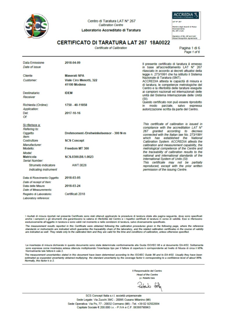
Page 1: cover page
The first page is in conformity with the ACCREDIA model: in addition to the Accredia logo, there is also the SCS logo. These logos are shown on each page of the calibration certificate. The page contains identification of the customer and information concerning the order, information on the instrument to be calibrated (type, model and serial number), date of receipt of the instrument and date of calibration, logistical information of the laboratory and authorized signature (the Head of the Centre or the Substitute).
 Page 2: informations
In the second page, in accordance with the Accredia model, further informations are provided:
– the reference standard
– the identification details of the Laboratory reference and its traceability (calibration certificate and uncertainties)
– identification and characteristics of the amplifier connected to the reference
– cable and adapters characteristics
 Page 3: informations
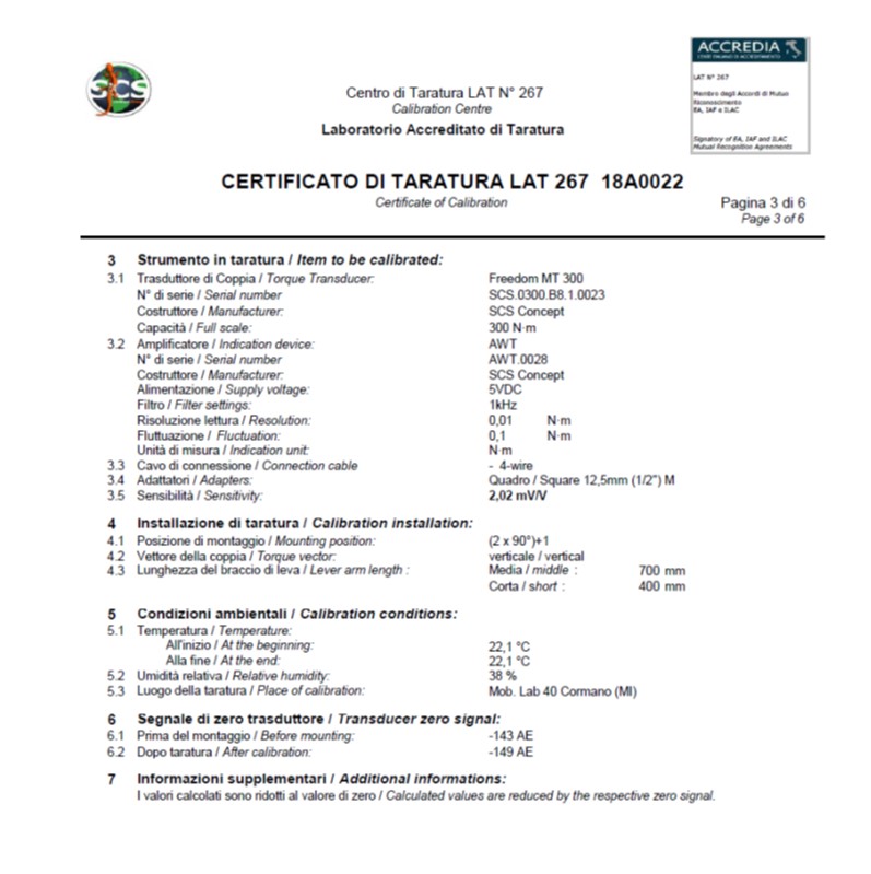
The following informations are detailed:
characteristics of the instrument to be calibrated, its amplifier, cables, adapters, sensitivity, calibration installation, environmental conditions, calibration location (in case of external calibrations) and zero signal value, before and after calibration, and any other information related to calibration.
 Pagina 4: calibration and classification results
On this page are shown the uncertainty values in relation to the linear interpolation curves (clockwise and/or counterclockwise) and, as in this case, the uncertainty for instruments at a defined scale.
The second table provides the classification according to DKD-R 3-8 according to the parameters contained in table 9 on the next page.
 Page 5: linear equation, classification criteria and measured values
• On this page are present:
• The linear equation for the separate clockwise and counterclockwise values and the linear equation for the common values
• Table 10 shows the values calculated for the various classification parameters
• Table 11 shows the measured torque values
 Page 6: results in diagram
• The first graph shows the relative error in the individual calibration steps
• The second graph shows the trend of the interpolation error

